Monday, December 9, 2019

bone conduction pen - ebay find - teardown


bottom line
cool gadget for its age
radio reception wasn't good
sound wasn't loud enough for my taste 
if i was building it with nowadays tech
i would probably think of using
small rechargeable lipo battery  
BLE capability - for phone connectivity
add a mic for a walkie-talkie (with push button)
much smaller design
for the vibration part there are multiple options
piezo, motor vibrator, conduction speaker etc
maybe even an array of those options for surround sound


Wednesday, May 15, 2019

eBay find lam research spectrometer and light source reveng

found this interesting looking item
was advertised as
Lam RESEARCH / EXCELITE PAX-10 Precision-Aligned Pulsed Xenon Light Source


what i saw was a setup of a light source and a spectrometer
had to find out what is it, even if it was a bit expensive
and so..

PAX-10 by excelitas xenon 10w light source


next thing was to find out what was the other unit, started to search some of 
the numbers and found some horiba / jobin yvon spectrometers images that looks similar
still needed to find the specific model, i think it is the VS-7000-CCD
but the specific model configuration specs is still a mystery


looks like the power is shared between the light source and spectrometer, 
signal is a DB9 plug that goes to the xenon light source and continue to the spectrometer,
usb belongs to the spectrometer


pinouts:

PAX-10:
pin 1 -- Vin
pin 2 -- Vin
pin 4 -- Trigger -
pin 5 -- Trigger +
pin 6 -- Gnd
pin 7 -- Gnd

Spectrometer:
pin 3 -- to main unit DB9 (pinout 3)
pin 5 -- Trigger +
pin 9 -- Trigger -

so looks like there is an option to trigger both the spectrometer
and the light source from the main DB9


a close look at the fiber optic tip
xenon light source is the outer fiber bundle
while the inner fiber goes to the spectrometer


next step was to find the power needs which i knew was somewhere between 11-28v
just because it was written on the PAX-10


first thing is to define the power polarity
next was starting at 11v and go up until ill find some signs from the usb


at 23v i saw a green led  light, rounded it to 24v as there isn't much difference
in between if you consider the power tolerance and 24 looks also more logical then 23
usb details:
idVendor 0x0c9b Jobin Yvon, Inc.
idProduct 0x000e


next step was checking the light source trigger was specify as 5v


100Hz and then 1Hz


looks like everything is working ,cool :) wasn't a complete waste of money
might even find a good use to this setup even if not in its current configuration
first thing will be to replace the power plug with a more common one
still need to source the spectrometer driver
to this moment didn't get any answer from Horiba / Lam RESEARCH

Monday, April 8, 2019

raspberry pi multi-spectral imaging system

I have been planning to build this for a long time. Once I had some free time I went to my local hacker/maker space (TAMI) and built this high resolution multispectral imaging system. The system is comprised from more than 30 different LED colors (up to a whopping 992 LED colors on a single i2c) and a dark room - box with top 1/3 aluminium foil (Styrofoam is another option) as close as I can get to evenly diffuse the light, and 2/3 bottom thin black cardboard (black velvet might be a better solution but couldn't find one locally) as close as i can get to no background reflection
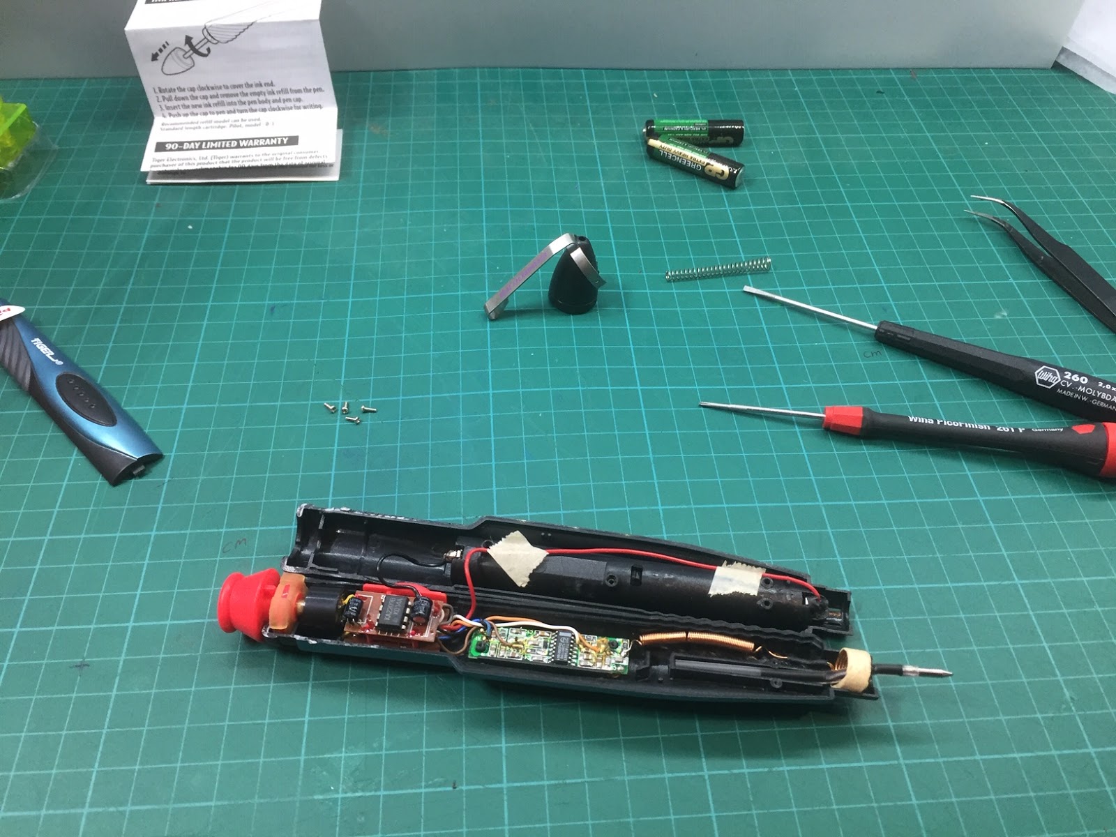
Its a simple design of multi color LED built in a series of 4 in order to get higher luminosity. I started with sourcing different colors of high intensity LEDs about 0.5usd each.


placed them all in a nice order on top of an aluminium sheet (heatsink)


Each of the LEDs series is connected to a mosfet and mux (pca9685), thinking about replacing the pca9685 with pca9635 (1khz vs 97khz) and adding a phototransistor for closed loop tweaking of the LEDs PWM. Might as well check the rise and fall time for each of the LEDs series. For the constant current source I used a single mean well LED driver (ldd-700h), for the controller at the moment I’m using a raspberry pi (code is at the bottom) built a nice dark box for them.


Tested them before installation


Some more testing (white a4 paper and a reflectance standard)


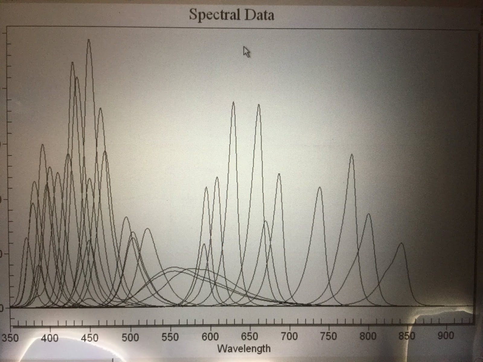
Tested all of the colors with a spectrometer ~370nm up to ~880nm and white 2.7k, 6k, 10k


Sorry about the screen photo, I got the x61t ips with the glue problem..
still need to drill a large hole at the center of the aluminium plate for the imaging part (ids monochromatic camera). Notes to myself: find a photodiode (FDS010 ?) to get real PWM value and light intensity photo-diode/transistor should match the LEDs spectra. Found a photodiode in my junk box (FDS10X10?, S2387-1010R? , 340nm-110nm ?)


So at the moment i hope it will be sufficient seems like the LTC1050 is a standard for converting the photodiode current to voltage.

A quick dirty phone video of the laptop screen (avocado leaf),taken with a monochromatic camera, no calibration yet or sync between the camera and the LEDs, sorry for that.


Imaging setup update:
Added a touch screen - still to be done is a fix for the eGalax driver (apt install xserver-xorg-input-evdev, edit /etc/X11/xorg.conf replace 'libinput' with 'evdev' ,apt install xinput-calibrator, swap x-y touchscreen axes).
Run everything from the same power source (LEDs driver 15v, screen 12v, pi 5v)


Drilled a hole


System test with a temporary camera mount


Picked some pieces of anodized aluminium from TAMI
and used it to build this adjustable universal camera mount


Update:
Its important that only reflected light from the tested object will enter the lens
so I measured the hole and found a suitble plumbing pvc tube that fit like a glove.
I cut it just too short to my taste (i figured the longer it will be the better end result)

measured hole


measured plumbing pvc tube


changed the lens for a wider FOV


Looks like an improvement has been done even if the tube should be much longer (guess something of at least 10 cm). I might extend it with a black cardboard temporary and wrap its outer side with an aluminium foil.


Painted it with black paint the outer part will be covered with aluminium foil once dried


Another video, this time its a grapevine leaf (LED intensity isn't calibrated yet!
and some bands are well absorbed by the leaf, plus it didn't help to have the
lens shutter almost fully closed. I will try to make a new video tomorrow or so)
The bore like image is due to a bit longer tube (20 cm) then wanted so that
the FOV (field of view) of the image is catching the end of the tube- on my to do list is to make an adjustable length tube for different lenses.


Screen capture (simplescreencapture)


Updated photo of the station


Added magnetic door latch


Another video, lost couple of frames due to lack of power of the raspberry pi, this time its a potato leaf, and some opencv image processing (CLAHE equalize and corresponding histograms)


while waiting for the nvidia jetson to arrive
i thought ill handle some of the cosmetics :)


and my present is ready to openly take multi-spectral images ;)


ill update the code once everything will be finished
but its a start to whom who has no patience to wait:
from __future__ import division
import time
import Adafruit_PCA9685
import cv2

from pyueye import ueye
import ctypes
import datetime

pwm = Adafruit_PCA9685.PCA9685(address = 0x40) #1st 
pwm1 = Adafruit_PCA9685.PCA9685(address = 0x41) #2nd
pwm2 = Adafruit_PCA9685.PCA9685(address = 0x42) #3rd
pwm.set_pwm_freq(1000)
pwm1.set_pwm_freq(1000)
pwm2.set_pwm_freq(1000)

spec = "avo_leaf" #name of speciment

led = [0,1,2,3,4,5,6,7,8,9,10,11,12,13,14,15,16,17,18,19,20,21,22,23,24,25,26,27,28,29,30,31]
lux = [1900,1901,1902,1903,1904,1905,1906,1907,1908,1909,1910,1911,1912,1913,1914,1915,1916,1917,1918,1919,1920,1921,1922,1923,1924,1925,1926,1927,1928,1929,1930,1931] #temporary initial value 0, 4095

for x,y in zip(led, lux):
    if (x < 16):
       pwm.set_pwm(x,y,0) #led on 1st mux
    elif ( x>14 and x<32):
       pwm1.set_pwm(x-16,y,0) #led on 2nd mux 
   elif (x>31 and x<33):
       pwm2.set_pwm(x-32,y,0) #led on 3rd mux
   else:
       print(x)
    hcam = ueye.HIDS(1)
    pccmem = ueye.c_mem_p()
    memID = ueye.c_int()
    hWnd = ctypes.c_voidp()
    ueye.is_InitCamera(hcam, hWnd)
    sensorinfo = ueye.SENSORINFO()
    ueye.is_GetSensorInfo(hcam, sensorinfo)
    ueye.is_AllocImageMem(hcam, sensorinfo.nMaxWidth, sensorinfo.nMaxHeight,24, pccmem, memID)
    ueye.is_SetImageMem(hcam, pccmem, memID)
    nret = ueye.is_FreezeVideo(hcam, ueye.IS_WAIT)
    if (nret == 0):
      print("camera")
    else:
      print("____problem!!!____")
    FileParams = ueye.IMAGE_FILE_PARAMS()
    FileParams.pwchFileName = spec + "_led_"+str(x+1)+"_cam_"+ datetime.datetime.now().strftime("%s") + ".bmp"
    FileParams.nFileType = ueye.IS_IMG_BMP
    FileParams.ppcImageMem = None
    FileParams.pnImageID = None

    nret = ueye.is_ImageFile(hcam, ueye.IS_IMAGE_FILE_CMD_SAVE, FileParams, ueye.sizeof(FileParams))
    if (nret == 0):
      print("camera")
    else:
      print("____problem!!!____")
    ueye.is_FreeImageMem(hcam, pccmem, memID)
    ueye.is_ExitCamera(hcam)

    if (x < 16):
       pwm.set_pwm(x,0,0) #led off 1st mux
    elif ( x>14 and x<32):
       pwm1.set_pwm(x-16,0,0) #led off 2nd mux 
   elif (x>31 and x<33):
       pwm2.set_pwm(x-32,0,0) #led off 3rd mux
   else:
       print(x)

All in all it is a fun project to build and I’m looking forward to begin revision 2.0: Replace the raspberry pi (~35$) with nvidia jetson nano (~99$), maybe add small ml training for contrast, rebuild the bottom half for better light absorption, source multiple color lasers, use fiber optics bundle for multiple angles and make the system portable (smaller / folding capability, battery powered).


update: Aug 26 2022
and watch their video