Thursday, May 14, 2020

teardown wireless serial adapter hps-120

teardown handyware handyport hps-120 serial transceiver
download datasheet link


General Descriptions:
The HPS-120 from HandyWave is a ready-to-use short-range wireless connectivity solution for
industrial. It provides the most economic and powerful way of cable replacement for the serial
communication systems.

1.2. Key Features
 No need of external host and software
 Easy of installation and use
 Supports configuration of the local device
 Supports configuration of the remote device via Over-the-Air
 Easy of maintenance
 Supports up to 100 meter (Line of Sight)
 Supports RS-232
 Supports Point-to-Point and Point-to-Multipoint Topology

1.3. Key Specifications
 Operation Frequency: 2.4GHz ISM Band
 Transmitted Power: Max 20 / Typical 16dBm
 Received Sensitivity: More than –80dBm
 Power Supply: DC +5 ~ +12V
 Current Consumption: Up to 200mA at DC 5V
 Operation Temperature: -20 ~ 70 C
 Dimension (w/o antenna): 35mm (W) x 65mm (D) x 16mm (H)
 Baud Rate: 1.2, 2.4, 4.8, 9.6, 19.2, 38.4, 57.6, and 115.2Kbps
 Antenna Interface: SMA Female
 Signal Interface: D_SUB 9 Pin Female


The SP3222E and SP3232E series are RS-232 transceiver solutions intended for portable or hand-held applications such as notebook or palmtop computers.
The SP3222E / SP3232E series has a highefficiency, charge-pump power supply that requires only 0.1µF capacitors in 3.3V operation.
This charge pump allows the SP3222E / SP3232E series to deliver true RS-232 performance from a single power supply ranging from 3.0V to 5.5V.
The SP3222E / SP3232E are 2-driver / 2-receiver devices.
This series is ideal for portable or hand-held applications such as notebook or palmtop computers.
The ESD tolerance of the SP3222E / SP3232E devices are over ±15kV for both Human Body Model and IEC61000-4-2 Air discharge test methods.
The SP3222E device has a low-power shutdown mode where the devices’ driver outputs and charge pumps are disabled.
During shutdown, the supply current falls to less than 1µA.


BC417143B interfaces to 8Mbit of external Flash memory. 
When used with the CSR Bluetooth software stack, it provides a fully compliant Bluetooth system to v2.0 of the specification for data and voice communications.. 
System Architecture BlueCore4-External has been designed to reduce the number of external components required which ensures production costs are minimised. 
The device incorporates auto-calibration and built in self test (BIST) routines to simplify development, type approval and production test. 
All hardware and device firmware is fully compliant with the Bluetooth v2.0 + EDR specification (all mandatory and optional features). 
To improve the performance of both Bluetooth and 802.11b/g co-located systems a wide range of co-existence features are available including two types of hardware signalling: basic activity signalling and Intel WCS activity and channel signalling

Tuesday, May 12, 2020

fix repair ebay find SG382 SRS rf signal generator and SG385 power supply

SG382 DC-2.025Ghz Stanford Research Systems

symptoms no 10Mhz at the rear output
front panel not responding
photos taken at later date but 
when i opened it for the first time it was covered
with heavy layer of soot black residue 
no scheme but there is the circuit description
which for this case was just enough
some pictures of the boards


the rear 10Mhz was fixed after replacing a faulty resistor 
R101 4.99kohm on the main motherboard
didnt have smd so i used a regular size instead 
but as long as it fixed the problem i was happy with it


the front panel was fixed after a short reflow of the spi ic's (U308, U309)


during the repair process i also accidentally shorted something
on the dc dc power supply SG385 (15V, 5V, 3.3V, -5V, -15V)
after some probing seeing half the expected voltages 
which was strange i traced the problem to LM358
which was shorting it was for the temp control 
also replaced the fan which looked tired


Tuesday, May 5, 2020

powering apple ipad 1st gen without battery from power supply

got a 1st gen ipad (A1337)
when i plugged it into a charger
the screen start blinking dimly 
opened it up using a flat screwdriver 
checked the battery using a multi meter
voltage was zero volts and for any battery its not good news
seeing the prices for a replaceable battery 
i decided its not worth the money to buy a new battery
and that im going to use a 5V 2A usb charger i have
so i used a cutting knife to cut around the battery carefully
cut carefully along the green line

then i de-soldered the two dead battery cells
soldered four wires to the battery pads after checking the polarity
stripes is positive (+) and solid is ground (-)

i drilled two small holes at the side of the ipad for the wires

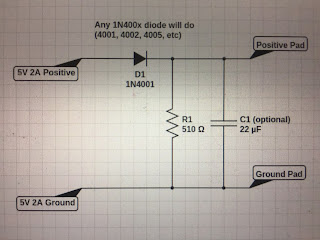
connected two diodes to the two positive wires
in order to decrease the voltage from 5v to about 4.3v
and two resistors between the positive and the negative wires
just to keep a small load on the diodes

the ipad still needed two quick jump-starts to boot
momentary connect and disconnect the usb charger
first jump-start showed an empty battery logo 

second jump-start started the ipad

success

now i have a useless 1st gen ipad running from a usb charger

 notes:
*used both battery pads and not single to share the load of the power consumption
*could use any kind of li-ion cell batteries instead of hooking it up to ac adapter
*battery manager comparing the voltages of the left and right cells and consume more from the higher one

Tuesday, March 31, 2020

monochromator stepper motor upgrade

upgrading a manual monochromator to scanning monochromator
using a small piece of alu some drill holes 
some screws stepper motor and shaft adapter 

some photos


augmented microscope

the basic peppers ghost scheme (taken from wiki)

the setup

had couple of problems with this one 
mostly illumination differences between
the microscope and the lcd screen
the perspex seems to double the picture -
might be solved with tint filter or swapping the perspex 
with a thin glass beamsplitter or ar coating
resolution wise numbers was pretty clear at 800 x 600
thinking about adding a button
to act as a shutter for the screen (on/off)

the setup:
the oscilloscope is hooked through the vga port
to a small lcd display that is mounted to the peppers ghost setup
where the transparent part of the peppers ghost (perspex sheet)
is placed at the view screen of the microscope

some photos (it actually looks much better in real life)

the peppers ghost periscope


testing the setup

without tint sticker

with tint sticker

some videos (it actually looks much better in real life)

without tint sticker

using a car tint sticker (applied poorly) did the trick
and solved the double reflection of the lcd in the above video
while not disturbing the actual image when the lcd backlight was off

with tint sticker


with tint sticker

for future development i would like to try 
adding a camera and or a microphone for interactive control 
image processing (probe gesture) or sound (click sound)
or show an overlay image only when a signal is being detected 
lcd backlight triggering / oscilloscope dmm triggering follow a click sound 
maybe hooking a foot switch, eye tracking camera and so on...

Saturday, March 28, 2020

augmented oscilloscope

the basic peppers ghost scheme (taken from wiki)

just an idea i had
of using peppers ghost illusion for electronics debugging
aiming a camera to the instrument that will be used
such as oscilloscope dmm or anything else
and displaying it on the transparent display

lcd screen with perspex at 45 degree angle (mirrored image)

aim the cameras to the desired instruments and display it on the screen

how it looks trough the perspex
i actually used a bigger setup (screen and perspex)
but with the same configuration
one disadvantage is that i didnt used the complete illusion setup
only one perspex so the actual image was mirrored 

some videos (looks better in real life)


for a better setup i would have use the complete peppers ghost setup
a bright screen / projector a mirror at 45 degree and a sheet of glass
and for the golden ticket use a transparent touch panel for easier control

transparent lcd mod

street find backlight  was bad so why not
only insight was that removing the anti-glare layer 
was meaningless and probably not worth the time and risk

no replacement parts

took apart

soaked with distilled water  to remove the anti-glare layer
(removing this layer is optional and not really required) 

tested against the window

added some leds around the screen